Yellow Box Install for speedometer recalibration
Yellow Box Install for MV Agusta F4S
Special Thanks to Yannis Doganis
The Yellow Box corrects speedometer error on motorcycles and cars which have had a change resulting in reporting error at the gauges. A wheel size change in cars and sprocket changes on motorcycles are frequent applications that can benefit from this correction. For motorcycles we require the 3-wire Yellow Box.
Things to buy:
(1) 3-wire Yellow Box speedometer recalibration device
--source: http://www.blackrobotics.com/
(3) Tab contact, part number (PN) 183024-1 $0.43 ea
(3) Receptacle Contact, (PN) 183025-1 $0.43 ea
(6) Yellow Seal Protector, (PN) 281934-2 $0.28 ea
(1) Housing Plug, (PN) 282087-1 $4.27 ea
(1) Housing Tab, (PN) 282105-1 $2.42 ea
(2) Boot, (PN) 880811-2 $2.51 ea
--source: http://www.onlinecomponents.com/
(2) 1m/3ft of Violet with white stripe 18ga stranded wire
(2) 1m/3ft of Brown 18ga stranded wire
(2) 1m/3ft of Blue 18ga stranded wire
--source: local electronics store
(3) Crimp butts or Crimp Solder Shrink butts
--source: local electronics store or web http://www.fastenerhut.com/catalog/default.php?cPath=1005_3600_3608_3670&osCsid=1c3d7576550f338648de79b6ce857530
(1) 1m/3ft of split loom, heat shrink tubing or flex conduit
Total cost ~ US $140 Total install time ~ 60mins
**Extra parts of the above as you see fit and to practice. We ordered extra of everything!
Tools needed:
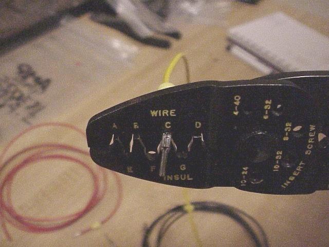
-AMP crimper
-Wire stripper
-Soldering iron if using regular crimp butts
-OR: heat gun if using Crimp Solder Shrink butts
References for factory wiring:
-Violet/white wiring on bike is switched power with key ON
-Brown wiring is the signal pulse from sensor up to gauge cluster
-Blue wiring is battery negative
References for AMP connector part numbers:
http://www.amp.com/ - enter each of the above part numbers for diagrams
We recommend reading over the “Installing the Yellow Box” which can be found on their website and is also included with the box itself.
Installation Process:
Remove left side mid-fairing and lift seat unit. Find speed sensor plug next to the water pump and unplug the AMP connectors (FIG 1). Pay careful attention to factory routing.
--FIG 1—
Locate the corresponding pins within each plug so that you can identify the wire colours (FIG 2). Note AMP Superseal parts are named “Housing Plug” on left and “Housing Tab” on right.
--FIG 2--
Next we’ll create a factory AMP connector interface to splice in the wires from the Yellow Box to the factory plugs. Locate all of your AMP parts ordered from onlinecomponents.com. *NOTE, photos do not reflect use of factory coloured wiring for the interface as it could not be found locally. Keep things organized in the same manner as described below if you do the same.
-Slide a yellow seal protector over the end of each of the (6) wires about 2cm in and with the small barrel side facing the end.
-Strip 5mm from the end of each wire.
-Crimp the “Tab Contact” and “Receptacle Contact” pins onto one each of the wire colours, e.g.: (1) Tab Contact to one Violet/White and (1) Receptacle Contact to the other Violet/White wire, (1) Tab Contact to one Brown wire and (1) Receptacle Contact to the other Brown wire, (1) Tab Contact to one Blue wire and (1) Receptacle Contact to the other Blue wire. AMP website shows how to correctly crimp. (FIG 3 and FIG 4)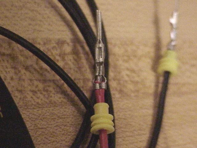
--FIG 3-- --FIG 4--
-Insert the (3) Tab Contacts into the three slots in the Housing Tab. Ensure Violet/White will plug into Violet/White, Brown to Brown and Blue to Blue. Please note there is a top and bottom for insertion and the contacts will SNAP once in place correctly. (FIG 5)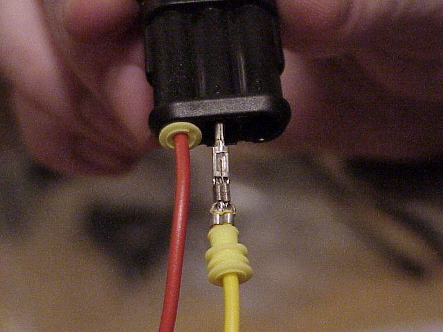
--FIG 5--
-Insert the (3) Receptacle Contacts into the Housing Tab in the same manner as above taking care to line up the wiring so that the corresponding colour matches the correct position on the factory mate.
-At your discretion bundle each side’s wiring with appropriate diameter heat shrink.
-Slide a boot over each of the bundles of wires so that you will end up with one boot per housing. (FIG 6) The boots fit over the housings to provide a tight fit.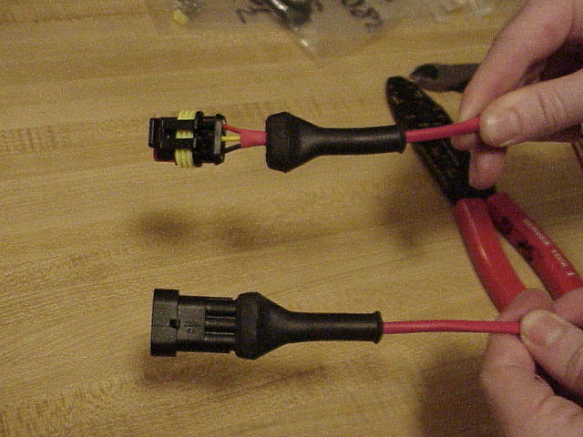
--FIG 6--
Our next step is to plug in the two newly made connectors to the factory mates. Where the topmost factory connector used to plug into the bottommost factory connecter we now have an effective interrupt to route to the yellow box.
Ensure all wiring connections line up with the same coloured factory wiring. See below for placement on the bike (FIG 7):
--FIG 7--
-Slide the entire bundle of wiring through your Shrink Wrap/Split loom.
-Route the bundled wire up and follow the route of the existing power wiring back to the ECU. This should pass under the frame, past the alternator, behind the gas tank, under the subframe, beside the battery and up the subframe to the ECU tray.
We will now prepare the yellow box side to connect all of our work thus far.
-Splice your (2) power wires (Violet/White factory) to the Yellow Box RED wire
-Splice your (2) ground wires (factory Blue) to the Yellow Box Black wire
-Splice your signal IN wire (factory Brown) from the sensor side to the Yellow Box White wire
-Splice your signal OUT wire (factory Brown) to the speedometer to the Yellow Box Gray wire. (FIG 8)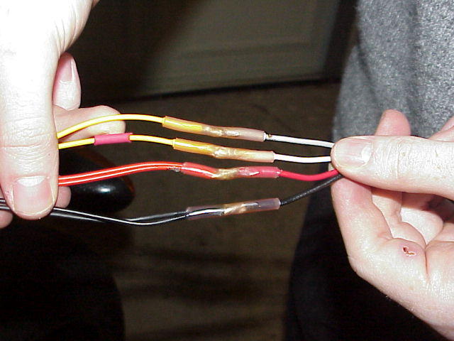
--FIG 8--
For my splicing I used Solder Shrink butts which, when heated via a hot heat gun, solder the wire together, heat shrink the butt connector and also release an adhesive agent to seal everything nicely. Plug in the newly spliced wiring to the yellow box.
Yellow Box secured to the ECU tray (FIG 9).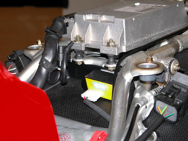
--FIG 9--
http://www.blackrobotics.com/yb_inst.htm (FIG 10)
Calibration is fairly straightforward with the most difficult bit being the determination of your bike’s % error. Using GPS I determined that both my speed and distance were 18% high. I had moved from a factory 15T countershaft sprocket and 40T rear sprocket to a 15T / 43T, a popular configuration.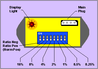
--FIG 10--
Using the Yellow Box switches I used switch 1 to indicate I wanted a positive change for a speedometer that was reading too high. A positive change means switch 1 goes RATIO POS or DOWN. This is somewhat counterintuitive but makes sense according to their instructions.
Next I simply added the appropriate numbers to arrive at a total change of 18%. I moved switches 2 and switches 5 to the ON position or UP. Turn the bike OFF to switch off power and allow the Yellow Box to calibrate.
Go out for a nice long ride to celebrate.
-JamesC
posted by MV FAQ @ 4:10 PM
2 Comments
![]()

2 Comments:
there are rumours about another blackbox, thats even easier to install. will look for more info.
This blackbox does not need any wires modified!!
http://www.mvagusta-parts.com/shop/e_tachokonverter.html
Look also under motocorse third party supliers
Post a Comment
Subscribe to Post Comments [Atom]
<< Home