Tuning 1) Throttle Position Sensor (TPS) setup
-contributed by Brad with Moto-One Australia www.moto-one.com.au
MV Dealership, Workshop and Custom Eprom tuner
Moto One
1432 Dandenong Rd. Oakleigh Victoria Australia LMCT 7644
Ph: (03) 9568 0100
info@moto-one.com.au
Please contact Moto-One directly if you are interested in their custom Eprom tuning for MV! Their information can be found here:
http://moto-one.com.au/performance/index.html
*1000R/Senna1000 Owners see note about your 5Sm ECU TPS setup at the bottom of this document
*Please note, this procedure is not specified by the factory - the factory specifies that the TPS (and any other related mechanism with yellow paint over the screw) should not "need" adjustment. I will include the factory procedure at bottom for reference.
This is a 2 part process for regular maintenance or *3 if you are also swapping the Eprom to tune:
- 1)TPS setup - this current document
-*2)Custom/Aftermarket Eprom swap - found here:
http://mvfaq.blogspot.com/2005/12/tuning-3-eprom-replacement.html
-3) Idle, CO and Throttle Body Balance - found here:
http://mvfaq.blogspot.com/2005/12/tuning-2-idle-base-co-and-throttle.htmlWeber Marelli Throttle Position Sensor Setting Notes and Procedures - with photos for MV - Written 11/05
When we service any bike with a Weber Marelli EFI system we have a set procedure to make sure it’s working as intended. Which may vary from working as well as it can (Moto Guzzi models in particular), but it’s the baseline setup that theoretically gets everything where it was when the mapping was created. First step in this is TPS setup. This is something that I learnt when I first started working at Moto and it hasn’t changed since. However, not all manufacturers detail it, and in the case of MV they seem to totally ignore it. Which is up to them, and really doesn’t worry me at all.
The Throttle Position Sensor has one job – it tells the ECU how far open the throttle butterfly is. Simple enough you would think. On the Weber Marelli systems the TPS is non linear (excepting Ducati 749, 800, 999 and 1000 models, which are linear - the ’05 620 is also linear TPS I believe). What this means is that the output varies in its sensitivity – at low throttle openings you get a higher voltage change per degree of throttle opening than you do at high throttle openings. This is just the way they do it. What this means is that for the ECU to read the output correctly there needs to be a baseline setting to reference the TPS and throttle butterfly so they’re both starting at the same point. Otherwise the sensitivity is off and you get variations not only based on incorrect base line, but also on the transient voltage/degree relationship.
We also do baseline setting procedures for BMW models (the zero = zero) and for the Ducati models with the linear TPS. Keep in mind both these procedures are not actually ‘official’, but they do work. These are based on correcting the baseline reference between the TPS and throttle butterfly – ie, when the throttle is fully shut the ECU reads it as fully shut, not open a bit or shut more than fully (not a physical, but an electronic thing). However, in the case of the Ducati models the output voltage from the TPS is not relevant, as you carry out an electronic procedure using the diagnostic software that tells the ECU that the voltage it is seeing corresponds to a certain throttle angle.
On the BMW models the voltage coming out is relevant, and is used to set the idle throttle angle. However, the BMW TPS is linear, using two variable resistor tracks to give sensitivity (which is why it has 4 wires). One track reaches max output voltage at about 25% throttle, the other at WOT.
The important point here is that the TPS setting needs to be done using a repeatable procedure that ensures they’re all the same. Once they’re all the same it makes everything that follows much more consistant. So what we’re after here is consistency – and the Weber Marelli non linear TPS system is the one that suffers from inconsistency the most.
At this point it’s worth mentioning that many see TPS position as a tuning variable. It’s not, it’s just a basic sensor with an expected system input, but for someone like me with access to lots of tuning equipment that’s easy to say. If you want to play with your TPS using your own method go for it, it’s your bike after all and not my problem.
All the procedures vary, but at their basis they all have some sort of ‘throttle fully shut’ setting. With the Weber Marelli non linear system, when the throttle is fully shut the TPS needs to be producing a voltage of 150mV. To check this voltage you need to get the throttle fully shut and hook into the TPS circuit with the ignition on (or use the Mathesis test function and separate lead). Once you’ve done that you then wind the idle stop up to give the nominal idle voltage. Ideally you then hook into the diagnostic connector and set the idle stop using a degree value as specified for that model. In this case we’ll work with the MV Brutale and carry out a setup specifically for our MVB01 Brutale eprom, although all the MV models share the same throttle body and TPS layout. The concept transfers directly to all the Ducati and Moto Guzzi models as well.
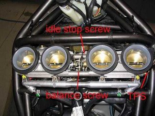
1/ First up, remove the tank, airbox, etc to allow access to the throttle bodies. The locations of required parts are shown. This procedure is usually carried out with all bits cold. A hot engine or throttle body will give a slightly different result. Which is more correct – cold or hot - I’m not sure, but convention is cold, and sticking to convention gives us repeatability.
click on photos to enlarge
2/ Slacken throttle opening cable (or remove the bracket on the throttle bodies) and dig out the yellow paint covering the idle stop screw at the front of the throttle bodies. There is another screw at the rear of the throttle bodies that sits on the end of this screw (see picture with 3/ below) – don’t bother winding it out as it often doesn’t wind out enough to allow the throttle to fully close. You need a 2.5mm hex key for this. Wind the screw out until there is 3 or 4 mm clearance.
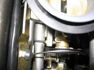
3/ Wind the balance screw 1 to 2 turns clockwise, remembering how much and where it was originally. This opens the LH throttle pair more than the RH, ensuring the RH throttle pair can shut completely without interference from the LH.
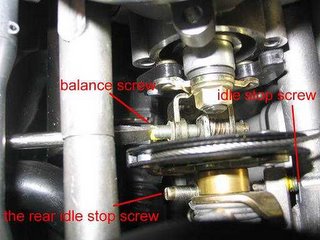
4/ Now you should be able to open the throttles and let them snap shut, or push down gently on the throttle blades themselves so they shut fully and lightly jam. This light jamming lets you know there’s nothing holding the throttle open.
5/ Move on to the TPS, located at the RH end of the throttle bodies. This is the later style small, round TPS on the MV that is also fitted to most Moto Guzzi after ’96, the Ducati 2V models from ST2 on and Ducati 748R, 996R and 998 models. All the previous models use the larger, square TPS, the very early ones (851, Daytona) of which were red. You can see the red painted screws, which we do after setting the TPS so we know for future reference that it has been done. As delivered these screws are covered in the same yellow paint that covered the idle stop screw. Dig out the yellow goop to ensure you get a good fit of the tool. On these later bikes they are a torx20 head, on early bikes usually a 7mm hex. The adjustment slots are visible behind the screws. There is a very large range of adjustment, why I’m not really sure.
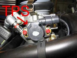
So now we need to measure the voltage coming out of the TPS and then move it as required to give the 150mV reading. There’s a few ways you can get into the TPS signal to check the voltage. We use an auxiliary function on the Mathesis tester and a special cable, but not many have that luxury.
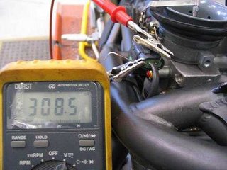
First is back probing the TPS itself. You need to take the voltage across the two outer wires for the MV. But you also need to make sure you don’t let the two probes touch or earth out on anything as this may give the ECU a voltage it doesn’t like. So be careful. Remember the ignition is turned on for this too, and you can see the display on the digital multimeter of 308mV. If you’re not sure if you have the right wires or not – the reading should be around 100 to 150mV with the throttle fully shut (as delivered) and it should rise to 4.85 or so Volts at WOT.
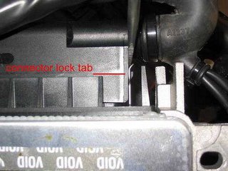
Second, and maybe somewhat easier when access is an issue, is reading the voltage at the ECU connector. This is relatively easy for P7, P8 and 1.6M ECU. First you disconnect the big black multipin connector from the ECU, levering the lock tab up with a small screwdriver. At this point always remember that when you turn the ignition off you need to wait at least 15 seconds before disconnecting the ECU.
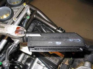
Then cut the zip tie holding the wiring boot on and pull the boot back exposing the end of the connector.
Remove the small Phillips head screw at the other end of the connector.
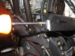
Now slide the outer cover off. When this cover comes off the two plates that lock each little connector into the multipin connector can come out, although I’ve never actually seen the little connectors come out. You can also see in this photo the numbers denoting each pin number for the ECU.
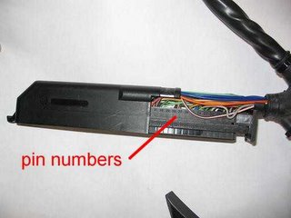
Now you can easily connect a multimeter into the backs of the terminals. In this case we want pins 16 (green with white stripe) and 30 (white with green stripe). For the older Ducati and Guzzi P7 and P8 ECU systems you need pins 11 and 17. Reconnect the multipin connector to the ECU, pushing it home firmly. Turn the ignition on and read the voltage.
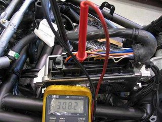
Once you’ve carried out the required TPS readings you reassemble the connector in the reverse and use a new zip tie to hold the rubber boot on. While this may seem a bit daunting the first time for some it’s not at all hard and I’ve never seen wires come out of a multipin connector. Not saying it couldn’t happen, and if it does don’t tell me it’s my fault.
As delivered, with the throttle fully shut, we expect the voltage to be from 150mV down to maybe 90mV. Occasionally it’s lower, and even more occasionally it’s higher than 150mV.
What you need to do now is loosen the two screws and rotate the TPS to give 150mV with the throttle fully shut. This is the baseline setting. Once you have a repeatable 150mV every time you open the throttle and let it snap shut (you should be able to get between 147 and 152 very easily) tighten the TPS screws and don’t touch them again. The TPS is now set.
6/ Wind the idle stop screw back in to give the idle setting. This setting varies for most models, and the relationship between this setting and what the ECU reads also varies. However, without the diagnostic equipment to read the degree setting (you need the Mathesis, Technoresearch or FIM software/tools to do this) the closest you can get is a mV setting. Be aware that a FIM Megazone or Ultimap eprom in a P7, P8 or 1.6M ECU will not talk to the Mathesis or Technoresearch software.
The table below gives a range of mV versus degrees – which oddly enough seems rather linear.

click to enlarge
For the MV Brutale 750 models the idle setting is 1.5 to 1.7 degrees – 315 to 335mV. I usually aim for 1.6 degrees.
For the MV Brutale 910 models the idle setting is 1.9 to 2.5 degrees - 355 to 413mV.
For the MV F4 year 2000 and 2001 the idle setting is 1.5 to 1.7 degrees – 315 to 335mV. I usually aim for 1.6 degrees.
For the MV F4 Senna, year 2002, 2003, 2004, SPR, SR the idle setting is 1.7 to 1.9 degrees - 335-355mV.
For the MV 1000 the idle setting is 2.1 to 2.3 degrees - 374 to 393mV.
Once you have the idle stop set as desired you don’t touch the idle stop again.
7/ Wind the balance screw (see step 1 and 3) anticlockwise (counter clockwise for our American friends) to return it to its original position.
You are not finished, move on to the following step which is correct for your situation.
To complete regular maintenance go to step 2):
http://mvfaq.blogspot.com/2005/12/tuning-2-idle-base-co-and-throttle.html
To swap Eprom as part of tuning go to step 3):
http://mvfaq.blogspot.com/2005/12/tuning-3-eprom-replacement.html
-Additional notes by MikeT, JamesC, yahoogroups
-blogged and edited: JamesC

0 Comments:
Post a Comment
Subscribe to Post Comments [Atom]
<< Home