Friday, August 26, 2005

Battery Problems, Tips, and Alternatives

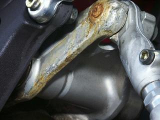
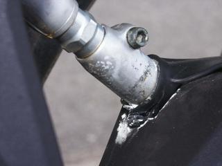
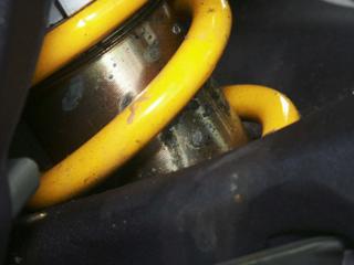
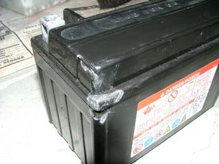
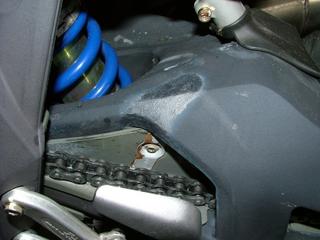
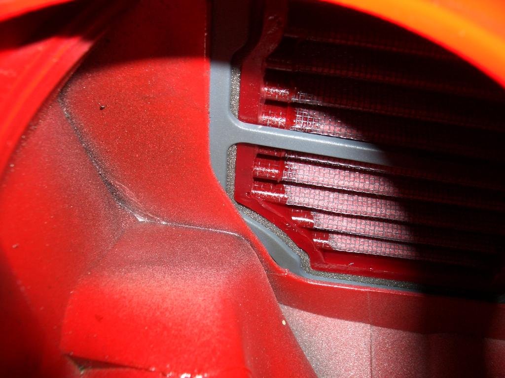
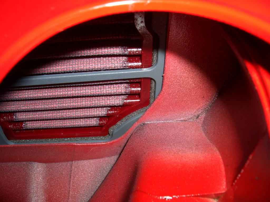
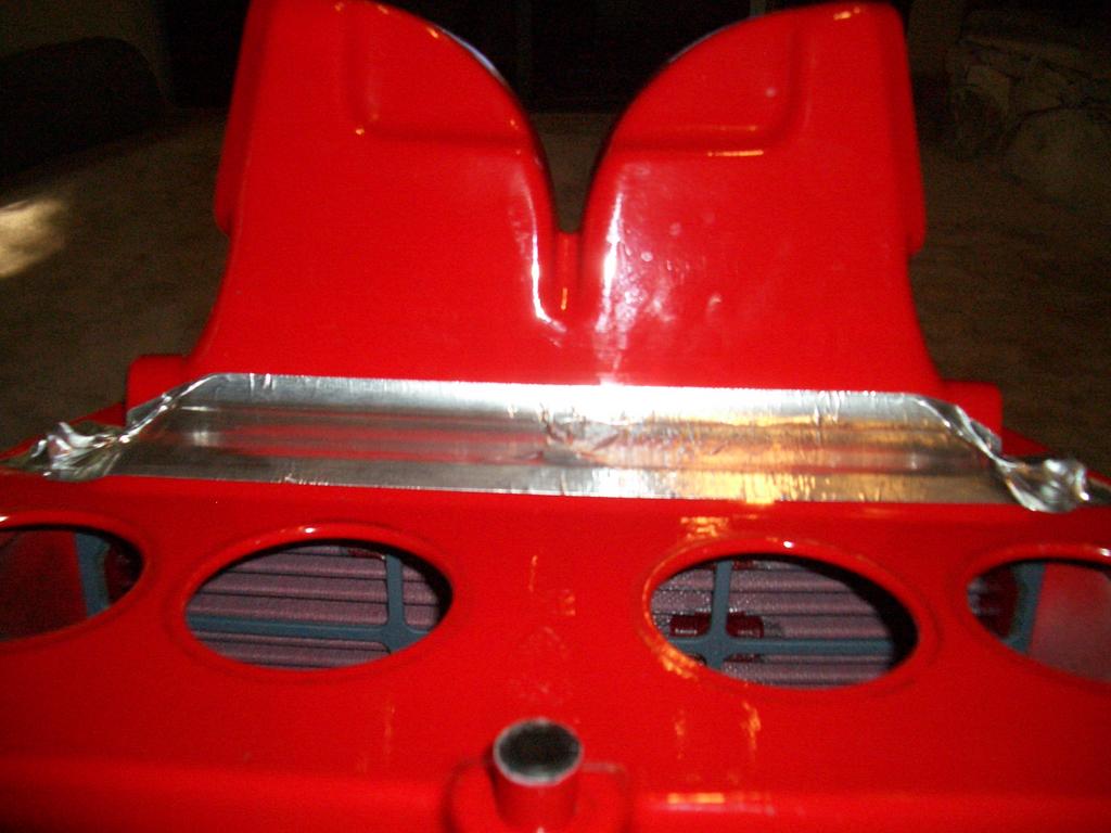
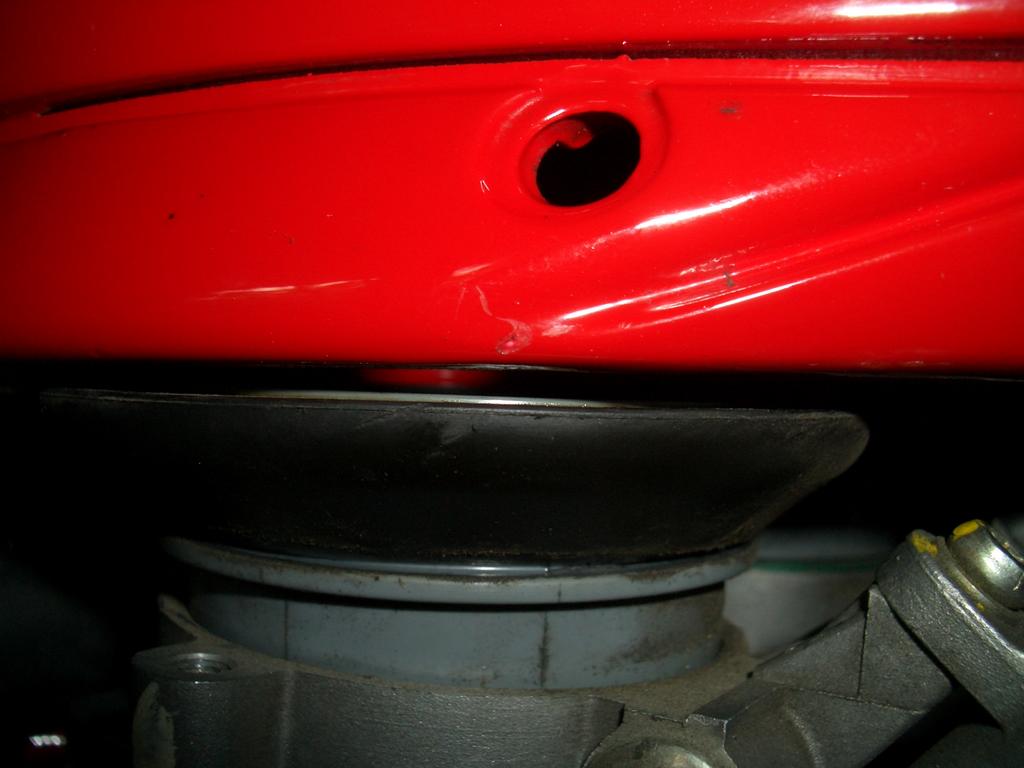
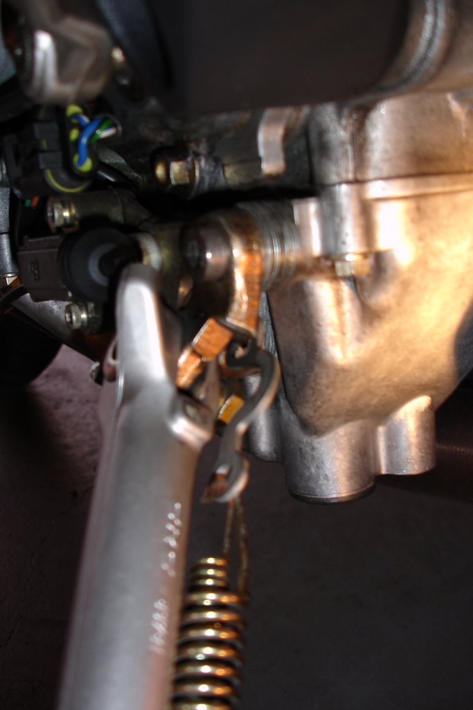
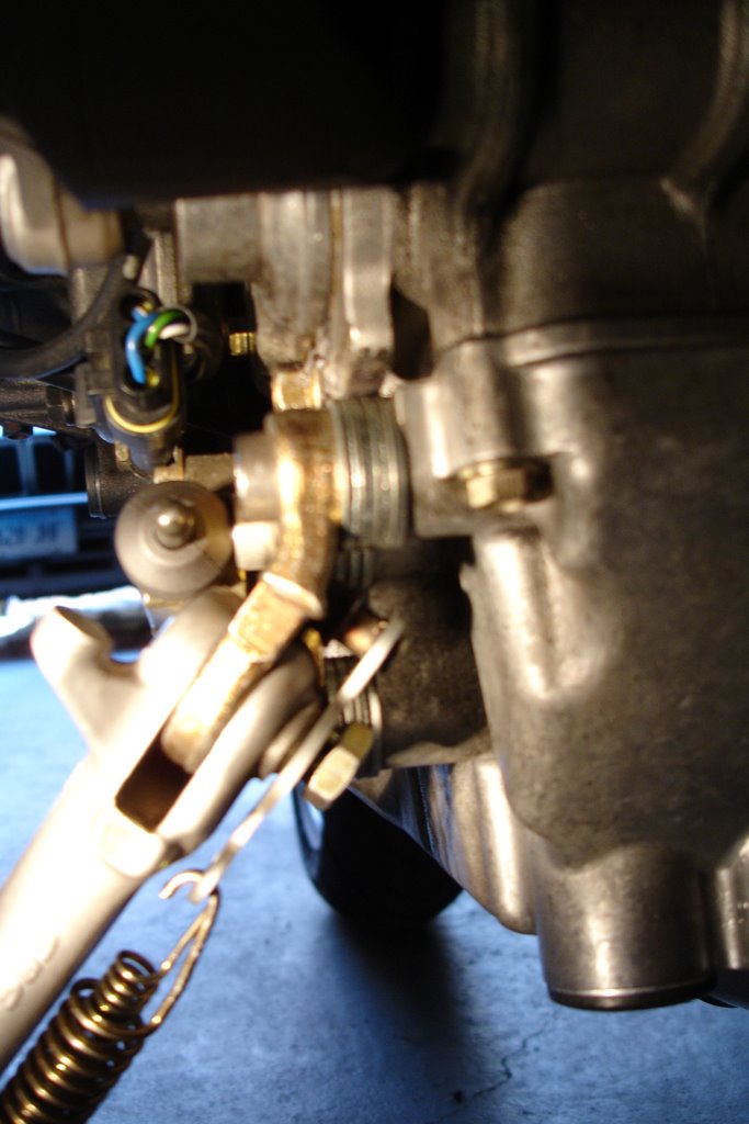
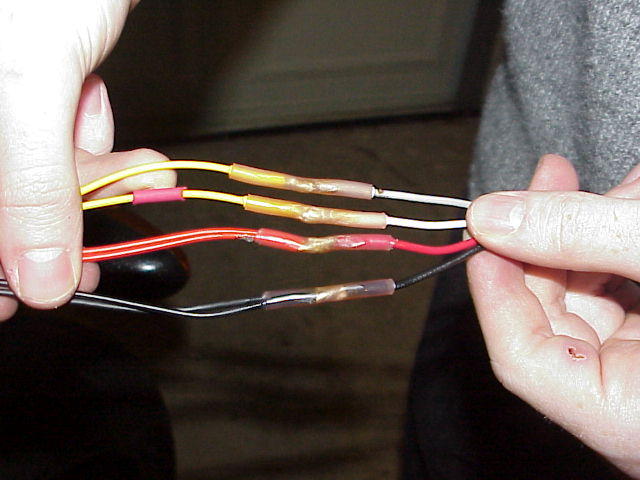
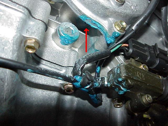
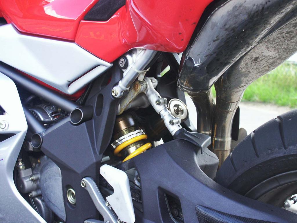
As you may have previously read, there have been some instances where the stock F4 battery has leaked causing damage to the rear shock and swingarm. After much discussion the consensus is that this is caused by improper battery preparation by some dealers and or owners. After filling, it is advised that you let it sit upright for 24 hours before capping and then on it's side for another 24 hours to allow sufficient time for out-gassing or it will build internal pressure and leak. It is not a pretty sight! (photos courtesy of John King)


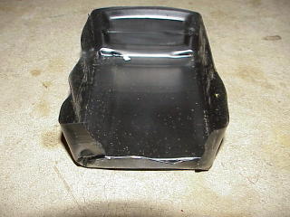
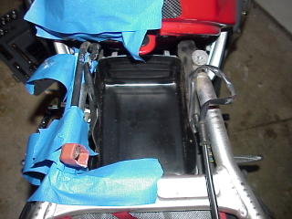
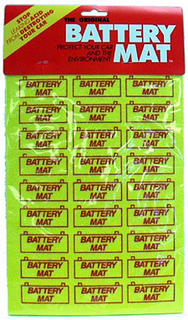
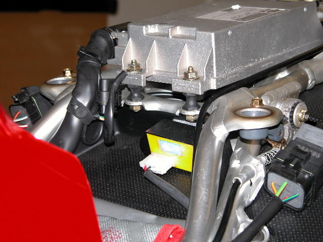
An empty plastic oil container can be used to make a containment tub which is set into the stock battery tray. An absorbent mat can also be added to the inside of this to help with spillage should it occur. (photos courtesy of James Corell)


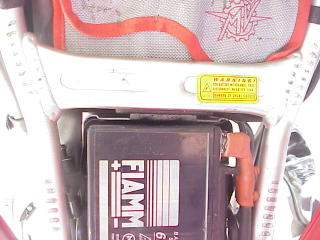
There are also some alternative replacement batteries that are available if you prefer not to use the stock FIAMM unit. Here is a starter list which will be added to as more info comes in:

Yuasa YT12A-BS which is also used on Suzuki GSXR 750 2000/2003 TL1000R 1998/2003 and GSXR 1300R Hayabusa 1999/2004

Yuasa YTZ10S used by MV as a factory upgrade and also used on Honda CBR954RR 2002/2003 and CBR1000RR 2004

Yuasa YTX9-BS which may be replaced by a Westco 12V9-B or a Bosch 508 012 088/0 097 150 80C (this is a UK sourced number and appears to be a dealer P/N for the unit)

http://www.apexbattery.com/yuasa-ytx9-bs-motorcycle-battery.html

Note: The above units are know as AGM (Absorbed Glass Mat) type batteries which are sealed and therefore should not spill acid on components although there have been a few occasions where this happened, please read below.

There's two problems that have come to light over here (Australia) with the new breed of batteries, you may already know that Ducati, Triumph, and some other brands have been having major warranty claims over these things since their introduction. Triumph is now sending all dealers world wide a rising rate charger for the pre-delivery (first charging of the batteries). This seems to get them to their max charge rate and helps them keep it over a long period as well. It is also known here that you have to leave the batteries after this charge to sit for 6 to 12 hours before fitting into a bike (more important if the battery lies on it's side in a bike like Dukes and MV's) as well or you end up with the gel leaking out. (courtesy of Paul from the Aprilia forum)

Here is some more battery/charger info that I found:

The "intelligent" chargers, used to "maintain" a battery assume thatthey are dealing with a "good" battery. For them, 2.4 VDC or even morethan that, is required to consider charging it and not declaring it BLR. Car chargers, especially the ones designed for dealing with "deepdischarged" batteries or the ones the dealers use to prime new freshly filled batteries could try to revive the battery and restore thechemical process. It seems that Mike's momentary reversing of polarityaccomplishes the same thing.

Basically 1.5 volts represent the full operating range of charge on a12-volt battery. It is possible to over discharge a battery well beyond its intended design. It is possible to take the battery voltage (on a 12-volt battery) down to 3 or 4 volts under load. That would constitute a severe over-discharge. Many batteries will not respond kindly to such abuse. Although if this only happens a few times, the battery voltage may recover to 8 or 9 volts without recharging. There is also a good chance that the battery can be restored to full health provided that it is recharged within a few hours of experiencing thesevere over-discharge.

Typically 11.4 volts represents 0% state of charge. Anything below11.4 VDC and the battery is discharged at a negative state of charge, or in other words, discharged at e.g. 120% or 150% of rated capacity.Without knowledge of very recent severe over-discharge conditions, one could make a judgment about the condition of the battery by a voltage measurement. If the battery voltage on a 12-volt battery is only 8 or 9volts, when measured in a rest state, then there is a very good chance that battery is defective. At the very least it is safe to say that the battery has been severely over-discharged. That's probably what Phil's optimate was reporting. Now if you charge it right away and do it correctly (voltage over time as required by the battery type) you have probably saved the battery, albeit with some scars left in it.

Also, getting back on the leaking battery issue, I thought of another potential culprit. A cheapo, defective or unsuitable (for AGM batteries) trickle charger or a bad voltage regulator. Basically something that tries to charge the battery at anything above 14.5 VDC, even for a short amount of time. This is called gassing voltage and you probably can guess by the name what it does to the battery. The gasses produced are more than the battery is designed to handle. (courtesy of the Yahoo forum)

Quick Easy Tip:

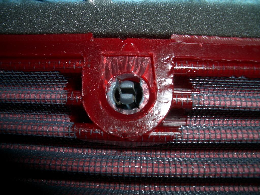
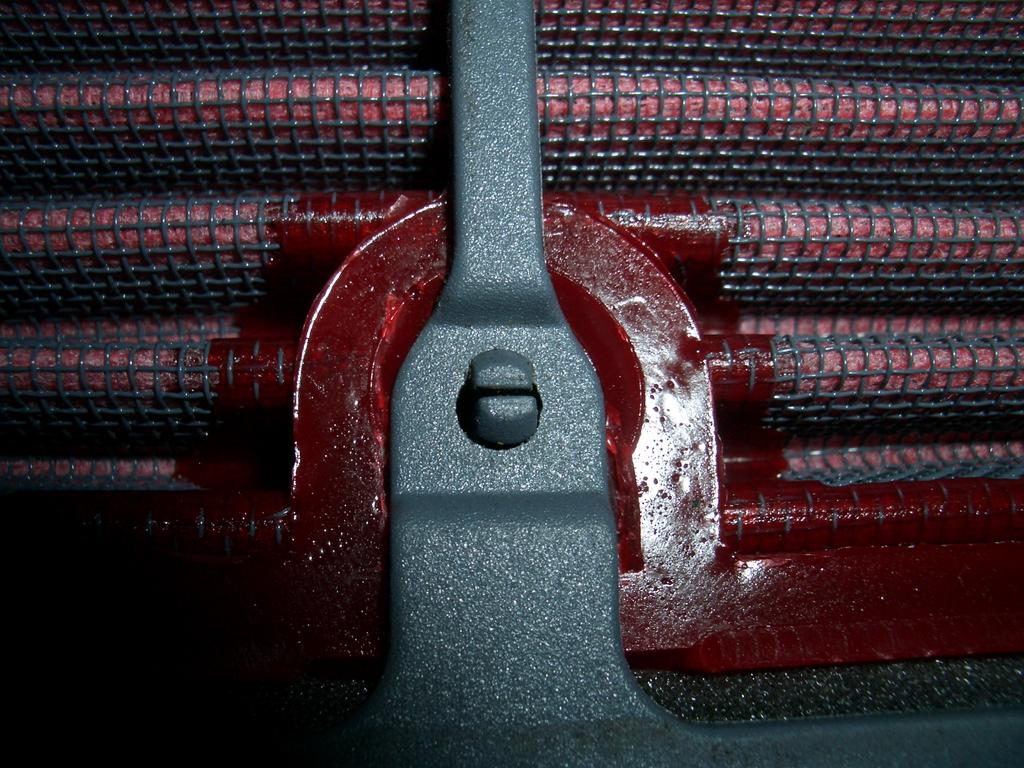
When installing the battery, and to hold the battery terminal nuts firmly in place and to prevent them from coming dislodged when the battery is tilted, cut a foam type ear plug in half (the cylindrical type) then squeeze it and slip it behind the nut. When it expands it holds the nut firmly enough to get it started. (courtesy of John Markis)

TGM

Thursday, August 25, 2005

Countershaft Sprocket (Pinion Wheel) Installation

Removal and installation of the countershaft sprocket is fairly straightforward with one noted exception.

Parts needed:
Stake Washer: 800081451

New Sprocket part varies by bike/year but note 2000/2001 bikes utilize a different sprocket offset than that of Senna/2002 and later bikes!

MY 2000-2001 Sprocket/Pinion Wheel:
800088340 =14 (standard)
8A0088340 =15
8B0088340 =16

MY Senna/2002/2003:
800098034 = 15 (standard)

There are two methods of removal. One (1) involves using the transmission in gear as force against which to remove the sprocket nut while the other (2) involves using the wheel and tire being bound as force against which to remove the sprocket nut.

REMOVAL PROCEDURE Alternative 1 (of 2):

-Put bike in gear

-Remove the chain from the bike
*Note loosen swingarm pinch bolts then utilize hub eccentric to loosen/slacken chain first
-Proceed to Procedure for sprocket cover and sprocket removal, below.


REMOVAL PROCEDURE Alternative 2 (of 2)


-Chock or tie rear wheel. You can accomplish this by tying the rim to your work stand or using the tire's friction against the work surface. Please note however that the loosening motion of the sprocket nut (left or counter/anti-clockwise will drive the wheel forwards and potentially off of the bike's sidestand.

-Remove the chain from the bike

*Note loosen swingarm pinch bolts then utilize hub eccentric to loosen/slacken chain first

Procedure for sprocket cover and sprocket removal:

-Remove the following 4 bolts (but not yet the cover itself)


Notice that three of these bolts are on the cover itself (10mm) and one is the left side of the clutch slave sylinder (8mm).

-Removal of the black speed sensor plug (AMP connection) may aid in clearing space.

IMPORTANT NOTE: This is the main gotcha for the procedure.
-To remove the counter shaft sprocket cover once the bolts are removed first slide the cover out just enough to get your fingers behind the cover. Behind the Clutch Slave Cylinder is the clutch actuation rod - as pictured below. This MUST remain inserted into the case and not be pulled out with the cover. I find it easiest to pull the cover just barely away then hold the rod with two fingers while sliding the cover off. It can be balky so be patient, it may take some slight rocking to help dislodge the rod from the cover. If you use needle nose pliers to help hold the rod in the case then cover with protective tape to keep from scoring the rod with the pliers.

-Once the cover is removed tie or tape it up to the frame so as to relieve pressure from the hydraulic line fitting.

Now the sprocket is revealed

Notice the clutch actuation rod (protruding) to the left of the sprocket. The stake washer as shown has also been bent back flat from it's locking position against the side of the nut. Yours should still be flush with one side of the nut.

-I prefer to remove the speed sensor wheel from the centre of the counter shaft, shown removed above (8mm?)

-Flatten stake washer to allow full access to all sides of nut

-Remove countershaft nut with 32mm or 1-1/4" socket. I found that a deep well socket was not needed if you remove the speed sensor wheel first. Standard threading so left or anti/counter-clockwise to loosen. Note any offset present on sprocket (Senna & 2002 onward) and remove stake washer then sprocket itself.

*This is a good chance to clean inside countershaft sprocket cover, speed sensor, chain guides, etc of any chain lube and grime

-Install new sprocket with offset, if present, on the engine case side (not facing you). Clean grooves in the shaft to aid installation, gentle tapping may be required to seat fully.

-Install new stake washer noting grooves in counter shaft

-Tighten counter shaft sprocket nut. Normal threading - tighten to the right or clockwise. 100Nm / 74lb ft.

-Bend portion of stake washer so that it sits flush with one entire side of the nut. A flat punch and small hammer will assist in full contact with the nut.

-Install new chain.

-Slide the cover back onto the clutch actuation rod and seat it firmly into the locating dowels. Take note to place the speed sensor wiring into the slot at bottom before continuing.

-Tighten the three 10mm cover bolts to 25Nm or 18lb/ft
-Tighten the clutch slave cylinder bolt to 8Nm or 6 lb/ft

-Reattach the black speed sensor connection

-JamesC

Tuesday, August 23, 2005

BMC Air filter installation into F4

A popular modification is the installation of a BMC air filter. In the USA our supplier is Fast by Ferracci.

www.ferracci.com

Part number for the F4 750 and 1000 is: F45800
Part number for the Brutale is: F45805
*NOTE that Europe has both a STANDARD and a RACE version available but in North America we seem to only have the RACE version.

The actual BMC filter part numbers are:
394/19 - for the street F4 filter
394/19 RACE - for the race F4 filter
360/19 - for the Brutale filter

Here is what FBF and BMC have to say about their filter:

"These high flow filters provide maximum protection, performance and quality. Developed in the high tech world of Formula 1 automobile racing. These filters clearly outperform more expensive paper and fabric type filters. BMC washable air filters are manufactured to higher tolerances than competing brands for maximum filtration area and flow rate. BMC incorporates parallel pleated cotton fabric and special filter oil to offer flow rates of up to 900 CFM."


PROCESS of INSTALLATION:

-Remove all bodywork
-Remove Tank
-Remove airbox
-Remove foil tape from air filter cage bottom
-Unclip the gray airfilter cage and remove OEM filter
*This is a good chance to clean out the inside of your airbox!

When your new BMC filter arrives it will have two packages. One including the foam weather stripping and another including the filter itself.

-Extract foam weatherstripping and filter from their packaging
-Place weatherstripping strips along the edge of each side of the air filter. Their contours follow that of the airfilter exactly
-Now you will need to modify the BMC air filter slightly so that it fits securely into the filter cage. Test fit the cage to see the exact outline that will need to be cut out. I used an X-acto knife, a razor blade will do.

Modify as follows


So that each component fits securely into the filter cage as shown. Only a few mm in thickness is removed. There are 4 holes to modify in total.


*Alternative method available. The Italian forum on Motociclando has been using a portion of toothpick to wedge between the barb and the hole to keep the cage assembled rather than making the time consuming cuts. I do not personally prefer this method for fear of toothpick bits being sucked into the engine.

-Next slide the assembled and foam weather proofed filter into the cage. Note position of orientation notch for BMC filter relative to the cage for correct front/back orientation.
-Slide the filter cage into the clean airbox until you hear all securing tabs click. Note position of filter cage notch for correct front/back orientation.
-Verify secure installation of filter and cage into airbox.


-Cover the bottom of the filter cage with foil tape


-Reinstall airbox taking care that the throttle body boots are secure against the bottom of the airbox openings. The factory suggests use of silicone grease between the rubber boots and the bottom of the airbox to ensure a good seal.

INCORRECT (note gap):


CORRECT (note lack of gap):


**Please note wellnut FAQ when re-installing airbox side covers. These should be replaced at each removal as they are ONE TIME USE.

-Reinstall Tank
-Reinstall bodywork
-Enjoy your new sound and increased breathing capacity!

JamesC

Side Stand Mod

This mod applies to early model MV F4’s with auto retracting side stands

Some folks either bend the stock spring lever around the existing nut such that the lower portion passes the centerline of the nut with the stand down or purchase the standard Evo 2 and up part number from Cagiva, but I have found the following method to work the best.

The Ducati spring lever [P/N 82912602A], or "side stand plate" as they call it, is very narrow and has a prominent 'C' in the middle of it that ends up fitting around the Ducati nut [P/N 75010481A], or "side stand bolt" as they call it, which has a slot turned circumferentially around it. Using these parts works great except you must also shim out the mount or the spring lever will scrape the belly pan as you put the stand down.


You will need to shim out the mount between 6mm to 7mm to provide the clearance needed. This is accomplished by using either a combination of appropriately sized washers or a length of tubing that serves as a compression sleeve. You will also need to replace the three 8mm x 22mm cap screws with longer 8mm x 30mm ones. If possible, try to use "low head" style cap screws otherwise one of them will rub against the rubber sensor boot and another will touch the fairing panel. I used standard 316 SS ones and trimmed the head height down to 6.5mm. Last, apply a little of the "removable type" loc-tite to all three screws and re-assemble.


Not only does this method cure the undesirable auto retracting problem but it also provides a bit more room for clearance and allows you to find the stand easier with your foot.


TGM

Monday, August 22, 2005

Wellnuts on airbox need to be replaced at every removal!

There have been at least two engine failures documented online due to airbox wellnut disintegration. The factory requirement is to replace the airbox wellnuts each time the covers are removed.

There are two wellnuts per side, one of which is towards the front of the bike and separated by the filter from the throttle bodies. The important one to this dicussion resides precisely above the #1 and #4 throttle butterfly openings. Direct passage for the small brass threads into the cylinder.

Orientation shows wellnut just above the throttle body.


In the following photo, looking closely, we can see that the wellnut has disintigrated upon removal of the screw:


From the inside:


Here we can see the brass thread core having separated from it's rubber sheath:


Part number: 800094651


Alternatives: Velcro. Industrial Blind nuts. 3M Dual-loc (found at Radio Shack for North American readers).

-JamesC

Yellow Box Install for speedometer recalibration

Yellow Box Install for MV Agusta F4S

Special Thanks to Yannis Doganis

The Yellow Box corrects speedometer error on motorcycles and cars which have had a change resulting in reporting error at the gauges. A wheel size change in cars and sprocket changes on motorcycles are frequent applications that can benefit from this correction. For motorcycles we require the 3-wire Yellow Box.

Things to buy:


(1) 3-wire Yellow Box speedometer recalibration device

--source: http://www.blackrobotics.com/


(3) Tab contact, part number (PN) 183024-1 $0.43 ea
(3) Receptacle Contact, (PN) 183025-1 $0.43 ea
(6) Yellow Seal Protector, (PN) 281934-2 $0.28 ea
(1) Housing Plug, (PN) 282087-1 $4.27 ea
(1) Housing Tab, (PN) 282105-1 $2.42 ea
(2) Boot, (PN) 880811-2 $2.51 ea
--source: http://www.onlinecomponents.com/

(2) 1m/3ft of Violet with white stripe 18ga stranded wire
(2) 1m/3ft of Brown 18ga stranded wire
(2) 1m/3ft of Blue 18ga stranded wire
--source: local electronics store

(3) Crimp butts or Crimp Solder Shrink butts
--source: local electronics store or web http://www.fastenerhut.com/catalog/default.php?cPath=1005_3600_3608_3670&osCsid=1c3d7576550f338648de79b6ce857530

(1) 1m/3ft of split loom, heat shrink tubing or flex conduit

Total cost ~ US $140 Total install time ~ 60mins

**Extra parts of the above as you see fit and to practice. We ordered extra of everything!

Tools needed:

-AMP crimper
-Wire stripper
-Soldering iron if using regular crimp butts
-OR: heat gun if using Crimp Solder Shrink butts


References for factory wiring:

-Violet/white wiring on bike is switched power with key ON
-Brown wiring is the signal pulse from sensor up to gauge cluster
-Blue wiring is battery negative

References for AMP connector part numbers:

http://www.amp.com/ - enter each of the above part numbers for diagrams

We recommend reading over the “Installing the Yellow Box” which can be found on their website and is also included with the box itself.


Installation Process:

Remove left side mid-fairing and lift seat unit. Find speed sensor plug next to the water pump and unplug the AMP connectors (FIG 1). Pay careful attention to factory routing.


--FIG 1

Locate the corresponding pins within each plug so that you can identify the wire colours (FIG 2). Note AMP Superseal parts are named “Housing Plug” on left and “Housing Tab” on right.


--FIG 2--

Next we’ll create a factory AMP connector interface to splice in the wires from the Yellow Box to the factory plugs. Locate all of your AMP parts ordered from onlinecomponents.com. *NOTE, photos do not reflect use of factory coloured wiring for the interface as it could not be found locally. Keep things organized in the same manner as described below if you do the same.

-Slide a yellow seal protector over the end of each of the (6) wires about 2cm in and with the small barrel side facing the end.
-Strip 5mm from the end of each wire.
-Crimp the “Tab Contact” and “Receptacle Contact” pins onto one each of the wire colours, e.g.: (1) Tab Contact to one Violet/White and (1) Receptacle Contact to the other Violet/White wire, (1) Tab Contact to one Brown wire and (1) Receptacle Contact to the other Brown wire, (1) Tab Contact to one Blue wire and (1) Receptacle Contact to the other Blue wire. AMP website shows how to correctly crimp. (FIG 3 and FIG 4)

--FIG 3-- --FIG 4--

-Insert the (3) Tab Contacts into the three slots in the Housing Tab. Ensure Violet/White will plug into Violet/White, Brown to Brown and Blue to Blue. Please note there is a top and bottom for insertion and the contacts will SNAP once in place correctly. (FIG 5)


--FIG 5--

-Insert the (3) Receptacle Contacts into the Housing Tab in the same manner as above taking care to line up the wiring so that the corresponding colour matches the correct position on the factory mate.

-At your discretion bundle each side’s wiring with appropriate diameter heat shrink.
-Slide a boot over each of the bundles of wires so that you will end up with one boot per housing. (FIG 6) The boots fit over the housings to provide a tight fit.


--FIG 6--

Our next step is to plug in the two newly made connectors to the factory mates. Where the topmost factory connector used to plug into the bottommost factory connecter we now have an effective interrupt to route to the yellow box.
Ensure all wiring connections line up with the same coloured factory wiring. See below for placement on the bike (FIG 7):


--FIG 7--


-Slide the entire bundle of wiring through your Shrink Wrap/Split loom.
-Route the bundled wire up and follow the route of the existing power wiring back to the ECU. This should pass under the frame, past the alternator, behind the gas tank, under the subframe, beside the battery and up the subframe to the ECU tray.

We will now prepare the yellow box side to connect all of our work thus far.

-Splice your (2) power wires (Violet/White factory) to the Yellow Box RED wire
-Splice your (2) ground wires (factory Blue) to the Yellow Box Black wire
-Splice your signal IN wire (factory Brown) from the sensor side to the Yellow Box White wire
-Splice your signal OUT wire (factory Brown) to the speedometer to the Yellow Box Gray wire. (FIG 8)


--FIG 8--

For my splicing I used Solder Shrink butts which, when heated via a hot heat gun, solder the wire together, heat shrink the butt connector and also release an adhesive agent to seal everything nicely. Plug in the newly spliced wiring to the yellow box.

Yellow Box secured to the ECU tray (FIG 9).


--FIG 9--


http://www.blackrobotics.com/yb_inst.htm (FIG 10)

Calibration is fairly straightforward with the most difficult bit being the determination of your bike’s % error. Using GPS I determined that both my speed and distance were 18% high. I had moved from a factory 15T countershaft sprocket and 40T rear sprocket to a 15T / 43T, a popular configuration.


--FIG 10--

Using the Yellow Box switches I used switch 1 to indicate I wanted a positive change for a speedometer that was reading too high. A positive change means switch 1 goes RATIO POS or DOWN. This is somewhat counterintuitive but makes sense according to their instructions.
Next I simply added the appropriate numbers to arrive at a total change of 18%. I moved switches 2 and switches 5 to the ON position or UP. Turn the bike OFF to switch off power and allow the Yellow Box to calibrate.

Go out for a nice long ride to celebrate.

-JamesC

Water Pump leaking

**Please note: MV has recently changed the water pump seals in question so we don't expect future issues. Please report if your 2006 production bike (or later) develops a leak. Email me at right or post a comment below.


There are two main causes of seeing blue (factory) coolant on the lower cowl. One of the first telltale signs:


Causes:

1) Normal coolant overflow from the overflow drain as seen here highlighted in red (ignore the rest for now):


The main cause of simple overflow is a reservoir overfilled. Keeping your reservoir at the MIN line (found below instrument cluster/clocks) is the usual prevention of this type of "leaking". Many owners also shut down their bike's engine but keep the ignition turned to on to allow the fans to run, thus cooling the radiators even after the ride. The normal turning off point is flexible but is often 185F /85C.


2) The second type of leaking is from the Water Pump itself, two internal parts in particular.

**NOTE: For 2006+ bikes or to retrofit the new pieces to your 2000-2005 bike please see section 3)


================================================
For 2000-2005 See numbers 10 & 23 below; per Factory Parts Manual section G07.
Click to enlarge:


The part numbers for the two points of failure (#10 & #23 above) are:


#10 800081236
#23 800081237

One contributor suggested preventative replacement O-ring while Water Pump is apart (#14 above) - though no others (+25) have required this part for successful fix:

#14 800086702

In ONE case a bike also required the shaft be replaced due to scoring, check your part for any abnormal scoring and replace if required. Part number is:

#9 800081539
==========================================================


3)
=================================================
2006+ bikes or to retrofit new design:

The factory have changed the water pump makeup to diverge from the previous design. They have moved from a shaft and two seals to a shaft and one seal as below (click to enlarge). See parts numbered 7 and 19:


The part numbers for the new design are as follows:
#7 8000A6709
#19 8000A6708
==================================================


The following photo shows the hole out of which the coolant escapes, see red arrow.


-JamesC

If you see this much coolant accumulated you may very well have a water pump leak. Now, what to do? Some owners, author included, have had the leak subside after 500-1000miles/800-1600km. If leak does not subside on it's own then replacement of the above two parts are known to resolve the very vast majority of leaks. Often, if under warranty, the factory will replace the entire unit rather than the two parts in question. This varies by geography.

-JamesC